

Electrical Panel Thermal Inspection: What Maintenance Teams Should Look For
Electrical panels are critical to industrial operations.
Switchboards, distribution boards, motor control centres and electrical cabinets distribute power to machinery, production lines, HVAC equipment and other essential systems.
A developing problem inside an electrical panel may not always be visible during a conventional inspection.
A connection can look normal while operating at an abnormal temperature. A circuit breaker may continue functioning even though one terminal is significantly hotter than comparable connections. An unbalanced electrical load may create temperature differences between phases without producing an obvious visual warning.
This is why electrical panel thermal inspection has become an important condition-monitoring technique for industrial maintenance teams.
Using a thermal imaging camera, technicians can visualise temperature patterns across energised electrical equipment and identify abnormalities that may require further investigation.
But successful thermography requires more than simply looking for the hottest object.
Maintenance teams need to understand what to inspect, what thermal patterns to look for and how to interpret what the camera is showing.
This guide explains the key areas to examine during an electrical panel thermal inspection.
What Is an Electrical Panel Thermal Inspection?
An electrical panel thermal inspection uses an infrared thermal imaging camera to examine the surface temperatures of electrical components.
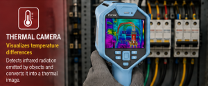
The camera detects infrared radiation and converts it into a thermal image representing temperature distribution.
Instead of seeing only the physical appearance of the electrical panel, technicians can see differences in surface temperature.
This can help identify abnormal thermal patterns around components such as:
- Circuit breakers
- Busbars
- Cable connections
- Terminals
- Fuses
- Fuse holders
- Contactors
- Relays
- Disconnects
- Motor starters
- Distribution connections
Thermal imaging is a non-contact inspection method, meaning the temperature information is obtained remotely rather than by touching the component.
However, thermal inspection of energised electrical equipment must always be performed according to applicable electrical safety procedures, risk assessments, safe working distances and PPE requirements.
Why Inspect Electrical Panels with a Thermal Camera?
Many electrical problems can produce heat.
For example, increased resistance at a deteriorating connection can result in localised heating when current flows through it.
Electrical loading conditions can also influence component temperature.
A conventional visual inspection might identify:
- Discolouration
- Physical damage
- Corrosion
- Loose components
- Contamination
But some developing problems may not yet show obvious visual evidence.
Thermal imaging adds another layer of information.
It allows technicians to ask:
Is this component operating at a different temperature from what we would expect?
That question is often more useful than simply asking whether the component is “hot.”
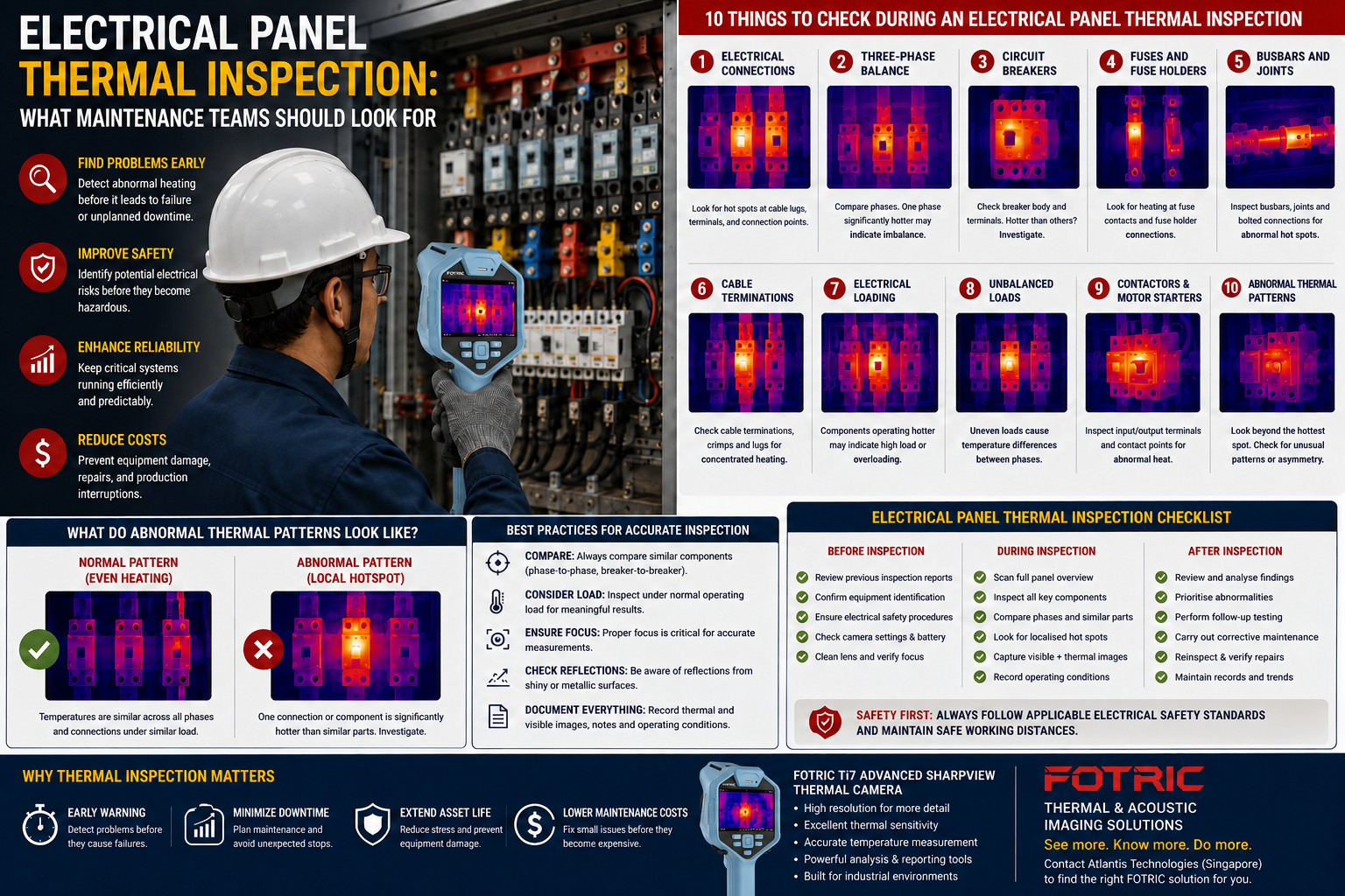
- Look for Hot Electrical Connections
One of the most important things to look for during an electrical panel thermal inspection is localised heating around connections.
Potential inspection points include:
- Cable lugs
- Terminal blocks
- Busbar joints
- Breaker terminals
- Contactor connections
- Fuse connections
- Disconnect terminals
A deteriorating electrical connection may develop increased resistance.
Under load, this can generate additional heat.
On a thermal image, the abnormality may appear as a concentrated hotspot around the connection point.
What Should Maintenance Teams Compare?
Whenever possible, compare the suspect connection with similar connections operating under comparable conditions.
For example:
If three phases use similar terminals and carry comparable loads, but one connection is noticeably hotter, the temperature difference deserves attention.
The thermal camera identifies the abnormal pattern.
Further electrical inspection is then required to determine the cause.
- Compare the Three Phases
Three-phase electrical systems provide maintenance teams with a useful comparison opportunity.
Under similar loading and operating conditions, comparable components across the phases may display broadly similar thermal behaviour.
A significant difference between phases can indicate that further investigation is necessary.
During an inspection, compare:
- Phase A vs Phase B vs Phase C
- Cable temperatures
- Terminal temperatures
- Breaker poles
- Fuse assemblies
- Busbar connections
If one phase is significantly hotter than the others, possible contributors could include:
- Load imbalance
- Connection resistance
- Component deterioration
- Other electrical abnormalities
Thermal imaging alone cannot determine which cause is responsible.
Electrical measurements and appropriate troubleshooting should follow.
- Inspect Circuit Breakers
Circuit breakers are another important target during electrical thermography.
Scan the breaker body, terminals and connected conductors.
Look for:
- One breaker hotter than comparable breakers
- Localised heating around a terminal
- Uneven temperature across poles
- Heating at the cable connection
- Unusual temperature patterns relative to electrical load
A heavily loaded breaker may naturally operate warmer than a lightly loaded breaker.
This is why operating context matters.
The objective is not to flag every warm breaker.
The objective is to identify temperature behaviour that appears abnormal for the operating conditions.
- Check Fuses and Fuse Holders
Fuses and fuse holders can develop thermal abnormalities around their connections and contact surfaces.
When inspecting fuse assemblies, compare similar fuses and look for:
- One fuse operating hotter than the others
- Heating concentrated around one end
- Hot fuse-holder connections
- Temperature differences between phases
- Heating around cable connections
A thermal anomaly can provide an early indication that the component should be investigated further.
- Inspect Busbars and Busbar Connections
Busbars carry substantial electrical current and are important inspection points in switchboards and distribution systems.
Maintenance teams should inspect:
- Busbar joints
- Bolted connections
- Branch connections
- Connections to breakers
- Connections to cables
- Phase-to-phase temperature patterns
A connection-related problem may produce a localised hotspot rather than uniform heating across the entire busbar.
This pattern can help technicians distinguish a possible connection issue from general load-related heating.
- Check Cable Terminations
Cable terminations are frequent inspection targets.
Look at:
- Cable lugs
- Crimped connections
- Terminal blocks
- Breaker connections
- Disconnect connections
A thermal pattern concentrated at the termination can indicate a condition requiring further investigation.
It is also useful to compare the temperature of the termination with the cable immediately downstream.
The shape and location of the thermal pattern can provide useful clues.
- Look for Signs of Overloading
Electrical current generates heat.
As loading increases, component temperatures may increase.
Thermal imaging can help identify circuits or components operating at higher temperatures than surrounding equipment.
However, temperature alone cannot confirm an overload.
If thermal imaging identifies a suspicious pattern, technicians should verify the electrical load using appropriate measurement equipment.
This illustrates an important principle:
Thermal imaging finds the symptom. Electrical testing helps determine the cause.
- Look for Unbalanced Loads
An electrical load imbalance can produce different temperature patterns between phases.
During inspection, compare corresponding components across all phases.
If one phase is consistently warmer, investigate whether the difference corresponds to electrical loading.
Thermal imaging makes this comparison fast because technicians can view several components simultaneously.
A clamp meter or other appropriate electrical instrument can then provide the electrical measurements needed for further diagnosis.
- Inspect Contactors and Motor Starters
Industrial electrical panels frequently contain contactors and motor starters.
These components may switch significant electrical loads and can develop thermal abnormalities at:
- Input terminals
- Output terminals
- Contact points
- Cable connections
Compare corresponding phases and similar equipment.
A localised hotspot around one terminal may indicate a different issue from uniform heating across the entire component.
Again, pattern recognition matters more than simply finding the highest temperature.
- Look Beyond the Hottest Spot
One of the most common mistakes in thermal inspection is focusing only on the maximum temperature displayed on the camera.
Temperature is important, but so is the pattern.
Consider these two examples.
Example A: Entire Component Is Warm
A breaker is uniformly warmer than neighbouring breakers.
Possible explanations could include higher electrical load or differences in component operation.
Example B: One Terminal Is Very Hot
Most of the breaker appears normal, but one connection shows concentrated heating.
This pattern may indicate a connection-related problem requiring investigation.
Both situations involve heat.
But the thermal patterns tell different stories.
Experienced thermographers learn to examine the distribution of temperature rather than relying only on the maximum reading.
Use Comparative Thermography
One of the most practical methods for electrical panel inspection is comparative thermography.
Instead of asking:
“Is 55°C too hot?”
ask:
“Why is this connection 55°C when two comparable connections are 35°C under similar conditions?”
The temperature difference may provide more useful information than the absolute temperature alone.
Useful comparisons include:
- Phase-to-phase
- Breaker-to-breaker
- Fuse-to-fuse
- Similar panels
- Similar motors
- Current inspection vs previous inspection
Comparative inspection can help reveal abnormal behaviour even when there is no simple universal temperature threshold.
Electrical Load Matters
Thermal electrical inspection is most informative when equipment is operating under meaningful load.
A deteriorating high-resistance connection may generate very little heat when almost no current is flowing.
As electrical load increases, the thermal symptom may become more visible.
For this reason, maintenance teams should understand the operating conditions during inspection.
Where appropriate, record:
- Current
- Load percentage
- Equipment operating state
- Ambient temperature
- Inspection time
This information can make future comparisons more meaningful.
Emissivity Can Affect Temperature Measurement
Thermal cameras measure infrared radiation, not temperature directly.
The relationship between emitted infrared energy and surface temperature depends partly on emissivity.
Different materials have different emissivity characteristics.
Painted and non-metallic surfaces are generally easier to measure than shiny bare metals.
Highly reflective electrical components can create challenges.
For example, a shiny metal busbar may reflect infrared energy from surrounding objects or even the technician.
This reflected energy can appear in the thermal image and potentially be mistaken for a real hotspot.
Thermographers should therefore understand emissivity and reflected temperature when making quantitative measurements.
Watch Out for Reflections
A bright area on a thermal image is not always a hot component.
Reflective surfaces can show thermal reflections.
One simple clue is movement.
If the apparent hotspot changes position as the technician changes viewing angle, reflection may be involved.
Real component heating normally remains associated with the physical component.
Understanding reflections is essential when inspecting:
- Bare copper
- Aluminium
- Polished metal
- Reflective busbars
- Metallic enclosures
Focus Matters
An out-of-focus thermal image may look acceptable at first glance, but poor focus reduces thermal detail.
This becomes particularly important when measuring small targets such as:
- Electrical terminals
- Cable lugs
- Fuse contacts
- Small connectors
Before capturing an image, ensure the target is properly focused.
Professional thermal cameras with autofocus can help technicians work more efficiently during large inspection routes.
Distance and Target Size Matter
A thermal camera may display a hotspot from a long distance, but that does not automatically mean the temperature measurement is accurate.
The target needs to occupy enough detector pixels.
A small terminal viewed from too far away may become averaged with cooler surrounding areas.
This can cause the measured temperature to appear lower than the actual target surface temperature.
When selecting a thermal camera for electrical inspection, consider:
target size + distance + infrared resolution + lens.
This is particularly important for substations, overhead equipment and other assets that must be inspected from greater distances.
What Should Be Recorded During an Electrical Thermal Inspection?
Good documentation turns a thermal image into useful maintenance information.
For each significant finding, consider recording:
Equipment Identification
Panel name, asset number or location.
Visible Image
A normal photograph helps maintenance personnel identify the exact physical component.
Thermal Image
Capture the abnormal thermal pattern clearly.
Temperature Information
Record relevant measurements and temperature differences.
Load Information
Where available and safe to obtain, document operating load.
Ambient Conditions
Record relevant environmental conditions.
Description
Explain what appears abnormal.
For example:
“Phase B cable termination shows localised heating compared with Phase A and Phase C.”
Recommended Follow-Up
Identify what further investigation or corrective action is required according to site procedures.
Electrical Panel Thermal Inspection Checklist
Maintenance teams can use the following basic checklist during inspections.
Before Inspection
- Confirm equipment identification
- Review previous inspection findings
- Confirm appropriate electrical safety procedures
- Check thermal camera settings
- Ensure camera lens is clean
- Confirm battery and storage capacity
During Inspection
- Scan the overall panel
- Compare all phases
- Inspect circuit breakers
- Inspect busbars
- Inspect fuses and fuse holders
- Inspect cable terminations
- Inspect contactors
- Inspect motor starters
- Look for localised hotspots
- Compare similar components
- Check for possible reflections
- Capture visible and thermal images
- Record operating conditions
After Inspection
- Review abnormal findings
- Compare with historical images
- Prioritise findings
- Conduct appropriate follow-up testing
- Perform corrective maintenance
- Reinspect repaired equipment
- Maintain inspection records
Thermal Severity: Should You Use a Fixed Temperature Limit?
Maintenance teams often ask:
“At what temperature is an electrical hotspot dangerous?”
There is no single temperature value that applies universally to every component and operating condition.
Severity assessment may depend on:
- Component type
- Temperature difference
- Electrical load
- Ambient temperature
- Comparison with similar components
- Equipment specifications
- Historical behaviour
- Applicable standards and maintenance procedures
For this reason, thermography programmes often use a combination of absolute temperature, comparative temperature difference and operating context.
The goal is to prioritise abnormalities intelligently rather than treating every warm component as an emergency.
Example: Three-Phase Breaker Inspection
Consider a maintenance technician inspecting a three-phase breaker.
The thermal camera shows:
Phase A: Similar to expected operating temperature
Phase B: Significantly hotter at the cable termination
Phase C: Similar to Phase A
Visually, all three connections appear normal.
The abnormality is concentrated specifically around the Phase B terminal rather than across the entire breaker.
This pattern gives the technician useful information.
The thermal image does not prove the exact root cause.
But it identifies where further investigation should begin.
The maintenance team can then follow appropriate safety and electrical testing procedures to determine whether the cause involves connection resistance, loading or another condition.
After corrective maintenance, the same area can be thermally inspected again.
Why Baseline Images Are Valuable
A thermal image becomes even more useful when there is something to compare it with.
During commissioning or when equipment is known to be operating normally, maintenance teams can establish baseline thermal images.
Future inspections can then compare current behaviour against previous conditions.
This helps answer:
Has this connection always operated at this temperature?
Is the temperature difference increasing?
Has the thermal pattern changed since the previous inspection?
Historical trending is one of the key ways thermal imaging supports predictive maintenance.
From Annual Inspection to Predictive Maintenance
Electrical thermography is sometimes performed only once per year.
Periodic inspection can be valuable, but the greatest benefit comes from integrating thermal imaging into a broader condition-monitoring strategy.
Critical assets can be inspected according to risk and operational importance.
Higher-priority equipment may warrant more frequent inspection.
Findings can be documented, trended and linked to maintenance actions.
Over time, the organisation develops a better understanding of normal and abnormal thermal behaviour across its electrical infrastructure.
This changes thermal imaging from a troubleshooting tool into a predictive maintenance tool.
Choosing a Thermal Camera for Electrical Panel Inspection
For electrical inspection, consider several important camera characteristics.
Infrared Resolution
Higher resolution provides more thermal pixels on smaller components.
Thermal Sensitivity
Good sensitivity helps reveal smaller temperature differences.
Focus
Accurate focus is particularly important for electrical terminals and other small targets.
Lens Options
Wide-angle lenses may help inside confined electrical rooms, while telephoto lenses can be valuable for distant equipment.
Measurement Accuracy
Professional electrical thermography requires reliable temperature measurement.
Visible Camera
A high-quality visible image makes findings easier to locate and document.
Reporting Software
Efficient reporting is important when inspecting many panels.
Inspection Workflow
For large predictive-maintenance programmes, asset identification, inspection routes and historical comparison can significantly improve efficiency.
FOTRIC Thermal Imaging for Electrical Inspection
FOTRIC provides professional thermal imaging solutions for electrical maintenance, industrial inspection and predictive maintenance.
Depending on the application, FOTRIC thermal cameras can support inspection of:
- Switchboards
- Distribution panels
- Circuit breakers
- Busbars
- Transformers
- Motor control centres
- Electrical connections
- Industrial machinery
Different FOTRIC platforms provide different combinations of infrared resolution, thermal sensitivity, autofocus, lens options, measurement capabilities and predictive-maintenance workflow features.
For general industrial maintenance, compact thermal cameras can provide a practical inspection solution.
For professional electrical thermography, higher-resolution systems with advanced focusing and optics can provide greater flexibility.
For large predictive-maintenance programmes and demanding inspection distances, higher-performance systems can support more detailed thermal analysis and asset-management workflows.
Thermal Imaging Is Only Part of Electrical Safety
Thermal imaging provides valuable information, but it does not make electrical work risk-free.
Inspection of energised equipment must be performed by appropriately qualified personnel following applicable safety procedures.
Thermal cameras should never be used as justification to ignore:
- Electrical risk assessments
- Safe working distances
- PPE requirements
- Arc-flash precautions
- Site procedures
- Equipment-specific safety requirements
The advantage of thermal imaging is that it provides temperature information without requiring physical contact with the measurement point.
That benefit should always be used within a properly managed electrical safety programme.
What Maintenance Teams Should Remember
Successful electrical thermography is not about finding colourful thermal images.
It is about identifying abnormal thermal behaviour.
During an electrical panel inspection, remember to:
Compare phases.
Compare similar components.
Look at the shape of the thermal pattern.
Consider electrical load.
Watch for reflections.
Ensure proper focus.
Consider target size and distance.
Document the finding.
Investigate the root cause.
Verify after repair.
When these practices are applied consistently, thermal imaging becomes much more than a camera inspection.
It becomes a valuable part of electrical condition monitoring and predictive maintenance.
Find Electrical Problems Before They Become Failures
Electrical equipment often provides warning signs before failure.
The challenge is that those warning signs may not be visible to the naked eye.
A thermal imaging camera allows maintenance teams to see temperature differences across electrical components and identify unusual patterns while equipment is operating.
A localised hotspot at a terminal, an unusual phase-to-phase difference or a changing thermal pattern across repeated inspections can provide valuable information.
The earlier these abnormalities are identified, the more opportunity maintenance teams have to investigate, plan corrective action and reduce the risk of unexpected equipment failure.
Looking for a Thermal Camera for Electrical Panel Inspection in Singapore?
Atlantis Technologies provides FOTRIC thermal and acoustic imaging solutions in Singapore for electrical inspection, industrial maintenance, predictive maintenance and condition monitoring.
Whether your team needs to inspect electrical panels, switchboards, circuit breakers, busbars, transformers, motor control centres or other critical electrical assets, selecting the right thermal camera depends on factors such as target size, inspection distance, required thermal resolution, lens and inspection workflow.
Our team can help identify an appropriate FOTRIC thermal imaging solution for your electrical maintenance requirements.
Explore our FOTRIC Thermal & Acoustic Camera solutions (https://atlantistech.com.sg/atlantis-technologies-products/thermal-camera/thermal-imaging-camera/) or contact Atlantis Technologies at sales@atlantistech.com.sg to discuss your electrical inspection application.